Reading and Writing IO-Link Parameters on a CPX-E on a Rockwell PLC through EtherNet/IP
Introduction
IO-Link is the first standardized IO technology worldwide (IEC 61131-9) for communication with devices such as pressure sensors, electric actuators, RFID readers, light stacks, temperature sensors and many others.
The powerful point-to-point communication is based on the long-established 3-wire devices connection without additional requirements regarding the cable material. So, IO-Link is no fieldbus but the further development of the existing, tried-and-tested connection technology for devices. Source: (www.io-link.com)
Festo’s CPX automation platform and CTEU-EP communication node have the ability to add IO-Link devices (from Festo and/or third parties). Therefore, additional products can be added because IO-Link is fieldbus independent and can be integrated into all fieldbus systems. (This technical write-up will only discuss Ethernet/IP fieldbus).
These features, for supporting IO-Link, are only roughly documented in the standard manuals. This write-up is intended to support these additional features, specifically including how to set and read IO-Link Parameters.
- Download EDS files
- How to install EDS files?
- Configuration of the CPX-E-EP with Festo Automation Suite
- Setting basic parameters to CPX-E-EP
- Addressing concept
- Working with Device Web Page
- Adding the CPX-E-EP system in Studio5000
- Controller tags
- IO-Link Integration with Ethernet/IP
- Read parameters on an IO-Link device
- Write parameters to an IO-Link device
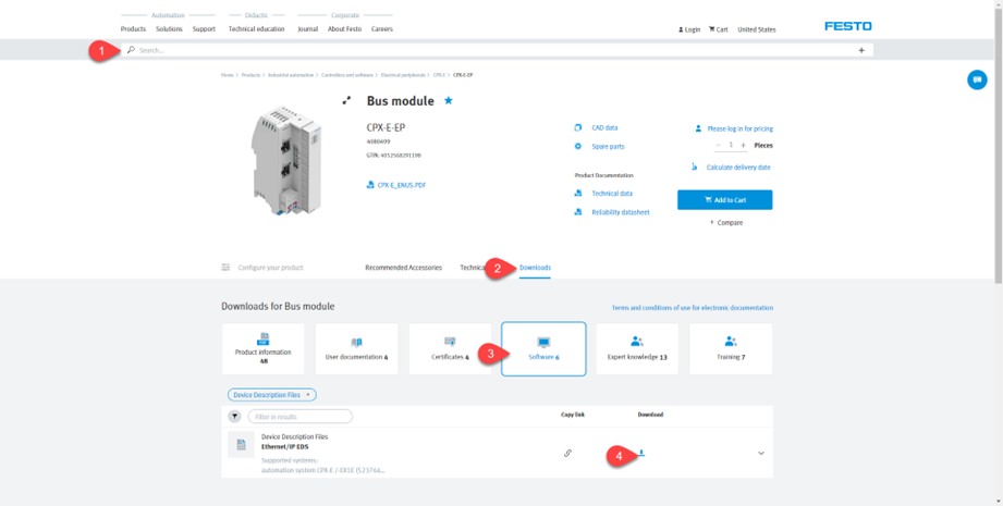
Download EDS files
- Visit www.festo.com and type the product code (e.g., CPX-E-EP) in the search field.
- Go to “Download”.
- Click on “Software”.
- Download desired file (e.g., Ethernet/IP EDS).

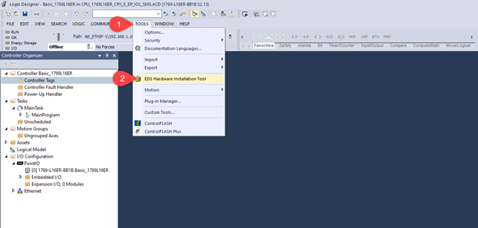
How to install EDS files?
- Once you have configured the PLC, download path and the basic PLC parameters, go to the tool bar. Select “TOOLS”.
- Select “EDS Hardware Installation Tool” from tools menu.
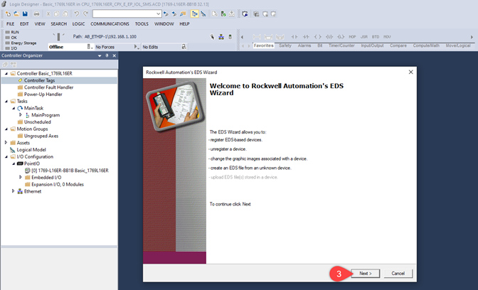
3. Read the instructions and click on “Next”.
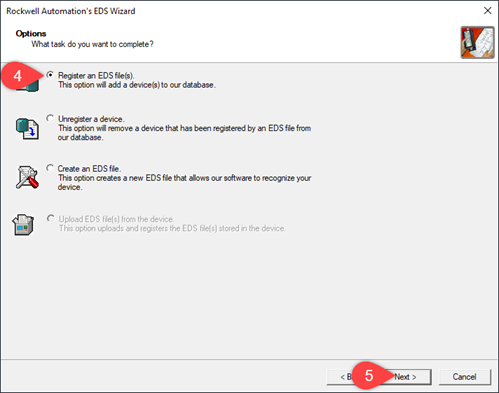
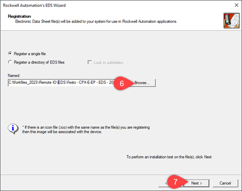
- Select “Register an EDS file(s)”.
- Click on “Next”.
- Click on “Browse…” and find the EDS file.
- Click on “Next” and follow the next steps.
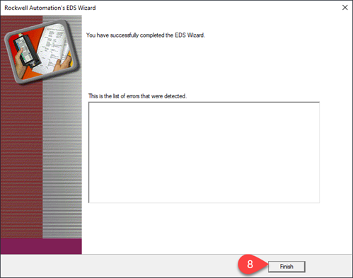
- Click on “Finish”.
Configuration of the CPX-E-EP with Festo Automation Suite
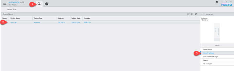
- Once you have opened Festo Automation Suite and started a new project, select “Device Scan” option in the top menu.
- “Select” the device you will be working with. (If your device has the correct network settings, please go to Step 5).
- Click on “Network Settings”.
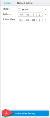
4. Disable (If desired) DHCP option and manually assign an IP address. Click on “Activate New Settings”.
- Add the device to the working project by clicking on “Add to Project”.
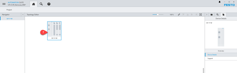
- Click on “Project Section” to go to the project view.

- “Double-click” on the device icon.
Setting basic parameters to CPX-E-EP
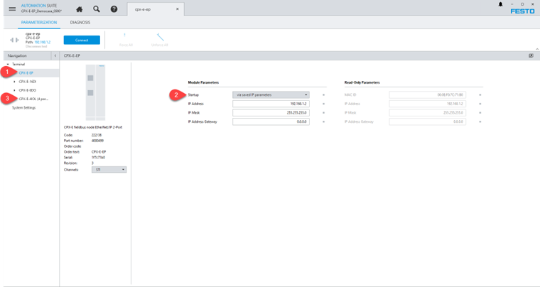
- When the CPX Plug-In starts, select the CPX-E-EP node in the “Navigation” section.
- Select “via saved IP parameters” option from the Startup drop-down menu.
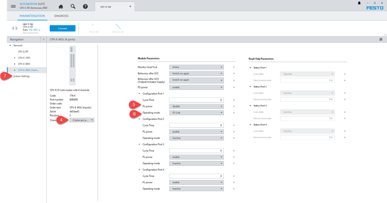
- Select “CPX-E-4IOL (4 ports) module from the “Navigation” section.
- Select the desired option, e.g., “2 bytes per port (Total 8 I / 8 O bytes)”. This option refers to the amount of Input / Outputs that the IO-Link device needs. In this example, it needs 2 bytes of inputs and 2 bytes of outputs.
- Disable “PL power” option. The device that we will test does not need this voltage for the load (outputs).
- Select “IO-Link” as the operating mode for port 1 (port to which the working device will be connected).
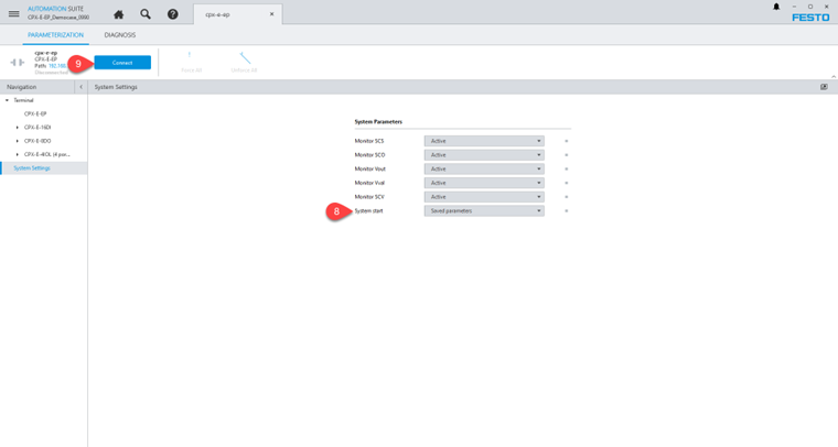
- Click on “System Settings”.
- Select “Saved Parameters” option from the System start section. This is to load the device with saved settings after a power cycle.
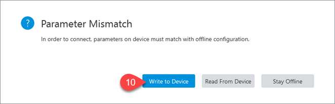
- Go online by clicking on the “Connect” button on the top bar.
10. Select the desired option. In this example we must save our project information into the device, so we will select “Write to Device”.
Addressing Concept
Address tags are classified into three types based on their functionality: Input, Output and Configuration. This topic discusses how to address the Digital and IO-Link modules in the PLC program.
Addressing format of the modules in the PLC program is 1:1 according to the physical slot position. Rearrangement depends on the module hardware type. CPX-E-EP module diagnose tags have priority in tags array. Technology modules are considered as second priority (e.g., IO-Link Master). Analog modules are considered as third priority and, finally, digital modules are considered as last priority in IO tag array position. For more detailed information, please refer to the CPX-E user manual.
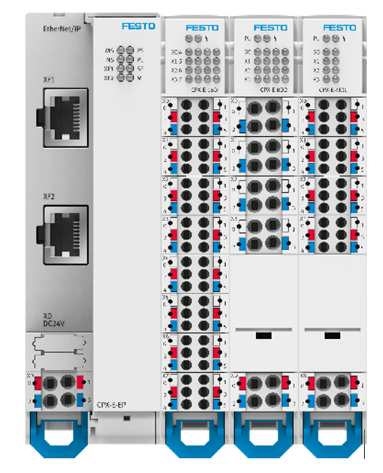
For example, consider the user has the hardware configuration displayed below. As per the HW configuration in the PLC Program, Input and Output tags are arrayed as shown:
Working With Device Webpage
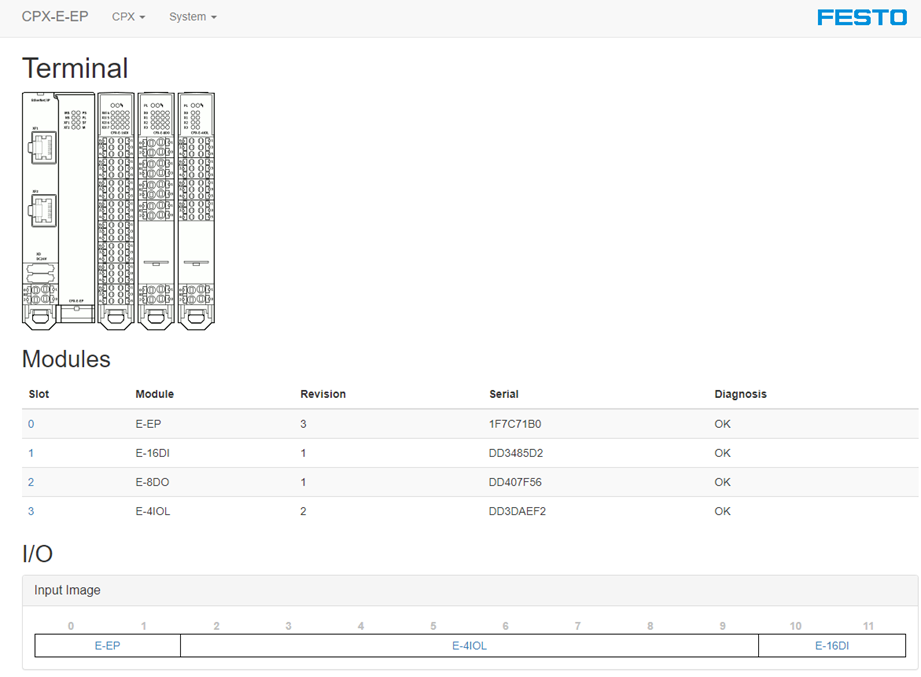
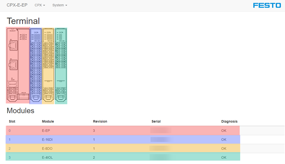
To access the “Device webpage”, type the IP address of the CPX-E-EP node (described in Festo Automation Suite, SCAN extension) or from this section by clicking on the “Open Device Web Page” option.
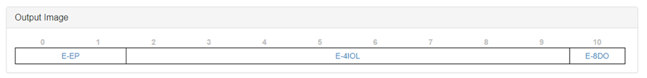
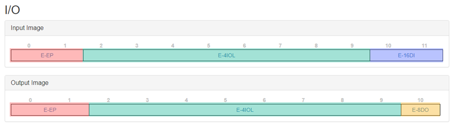
This section features a graphical representation of the hardware, the list of materials and slots from which it is composed and, finally, the In/Out arrangement according to the type of modules. (Here you will find the amount of input/output bytes).
As seen below, the example system consists of 4 slots and 12 input and 11 output bytes.
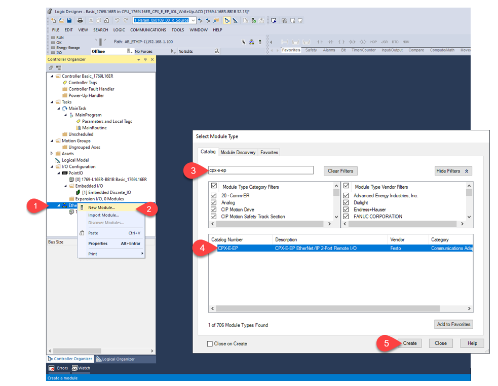
Adding the CPX-E-EP system in Studio5000
- In Studio5000, “right-click” on Ethernet.
- Select “New module…” on the display menu.
- In the pop-up window, type in the CPX-E-EP code.
- Select the desired device from the list.
- Click on “Create”.
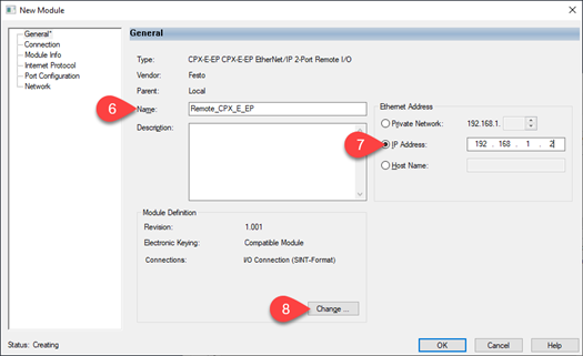
- Type the desired name for the device.
- Select the IP address that was set in Festo Automation Suite, via DHCP or via the “Hardware rotary switch”. Please refer to the product user manual for details.
- Click on the “Change…” section to open the module configuration (set the amount of I/O used by the CPX-E-EP system).
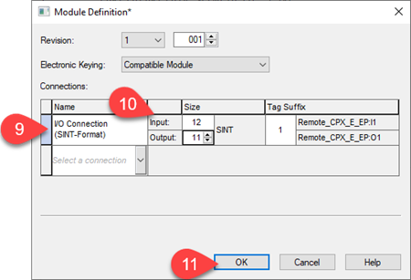
- Select the connection type (I/O Connection SINT-Format).
- Type the number of input/output bytes. In our system there are 12 input bytes and 11 outputs bytes.
- Click on “OK”.
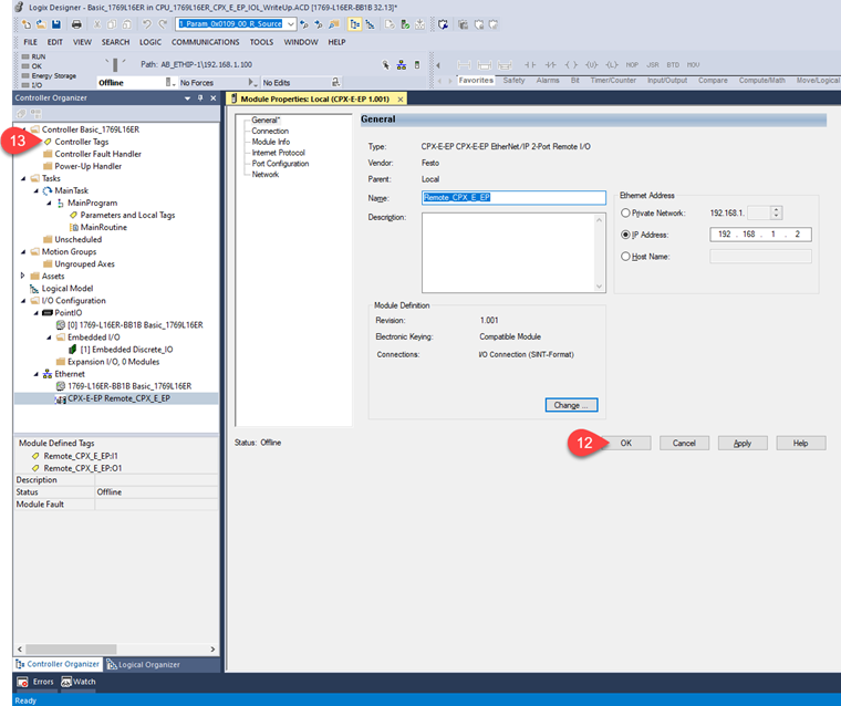
- Again, click on “OK” to finish the module configuration.
- Double-click on “Controller Tags”.
The CPX-E-EP system is already configured in Studio5000.
Controller Tags
Remember that the tags are reorganized depending on the type of hardware. In the following images we will see the type of module, the number of bytes used and how it looks like in Studio5000.
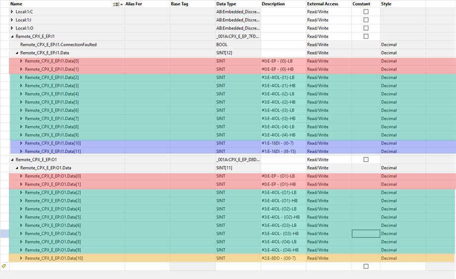
Due to the little-endian / big-endian difference in Ethernet/IP vs IO-Link, the byte order will be swapped. This must be handled in the controller logic.
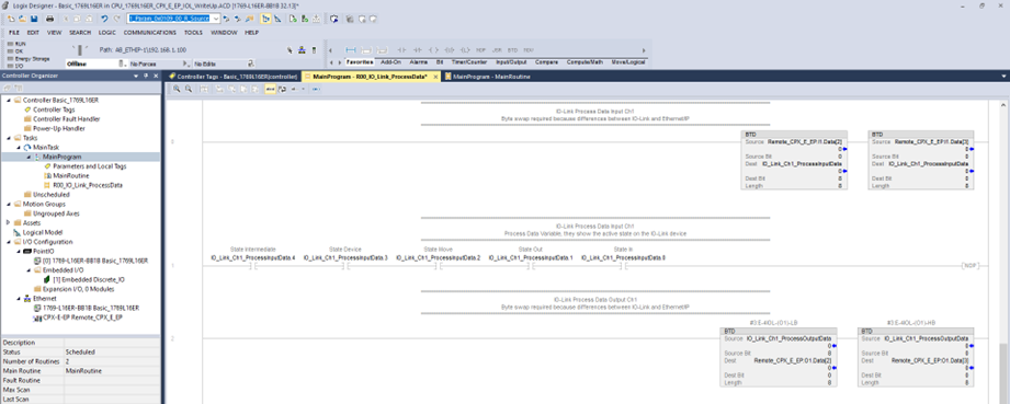
To do the byte swap we use the BTD (Byte Field Distribute) instruction, and the order of the status and control bytes (Process Data Input / Process Data Output) must be considered. This task must be done for the input and output data.
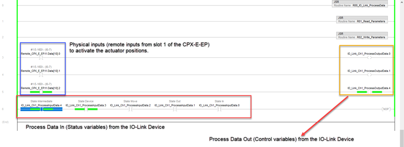
The image below shows the mapping of the input and output process data in the example IO-Link device Festo Simplified Motion Series electromechanical actuator EPCE-TB. (For more information, please refer to the corresponding user manual.)
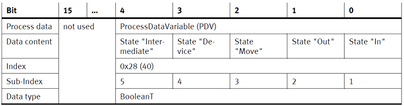
Process Data In
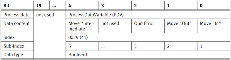
Process Data Out
So, in the most basic operation of this IO-Link Device, we can activate outputs or Process Data Out to execute movements. For example, if we activate bit 0 of the Process Data Out, the actuator will move to the “In” position and will send as feedback bit 3 (State “Device”) and bit 2 (State “Move”) of the Process Data In while it is moving. When it reaches the position it will send bit 0 State “In” and turn off the bit 2 (State “Move”).
Something that makes the IO-Link protocol very useful is the ability to read or write parameters to the device. In the following sections you will learn how to read or write parameters to an IO-Link device.
IO-Link Integration with Ethernet/IP
As described above, the behavior of the CPX-E system can be parametrized with Festo software or using a high-order controller. Here, a distinction is made between the following variants:
- System parameters
- Module parameters (module-specific and channel-specific)
- Parametrization of the diagnostic memory
You can find a detailed description of the individual parameters in the corresponding module user manual / product description.
The following section is an excerpt from the “Description / Function of the CPX-E-EP bus module manual” available on the Festo webpage. This is a representation of the CPX-E system within the Ethernet/IP object model.
The CPX-E system supports various services depending on the object:
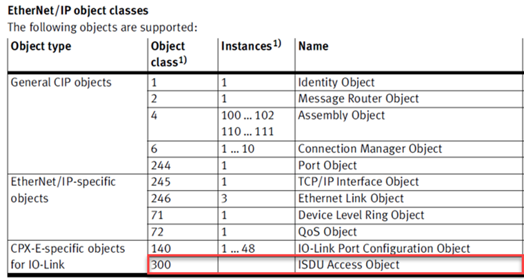
An IO-Link device can support parametrization via ISDU (Indexed Service Data Unit). In this process, the PLC must explicitly read or, when marked as such, write this acyclic service data.
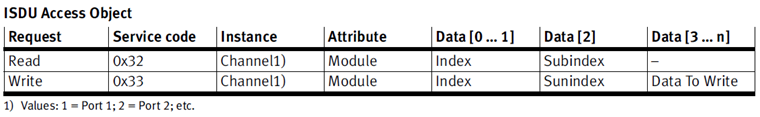
In the CPX-E system, the module or slot number corresponds to the “Attribute”. This value will be used in the “Message” (MSG) Instruction that we will use to access the read / write parameters from the PLC. Since MSG instruction must use the source element for the index number, one index at a time can be accessed.
Read parameters to an IO-Link device
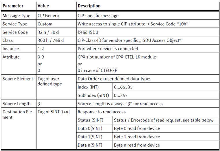
The following table shows the general message instruction requirements to read parameters:
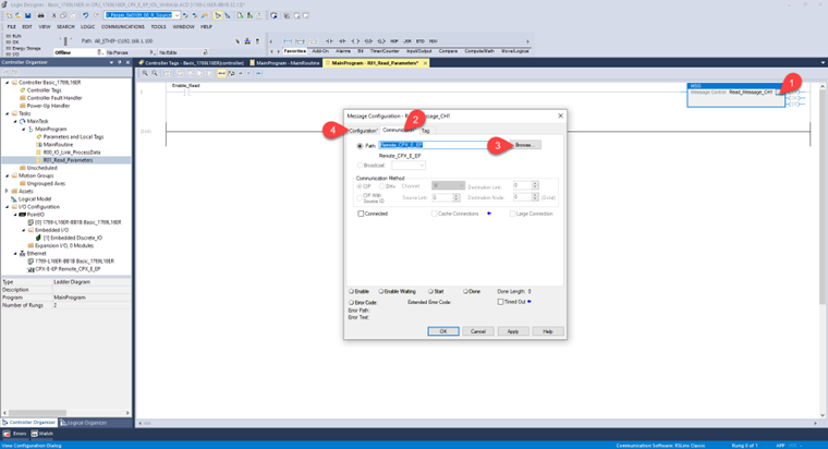
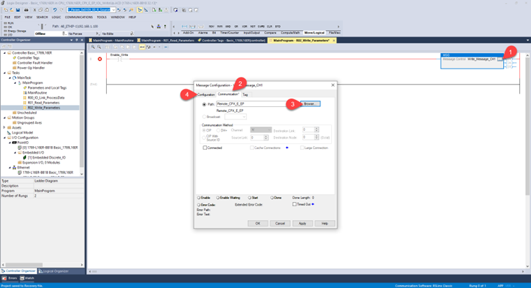
To add the MSG instruction to read parameters, we must:
- Once you add and name the MSG instruction (usually available in the group of elements: Input / Output), open the “Configuration dialog box”.
- Go to the “Communication”.
- Select “Browse…” and locate the CPX-E-EP system bus node in the path.
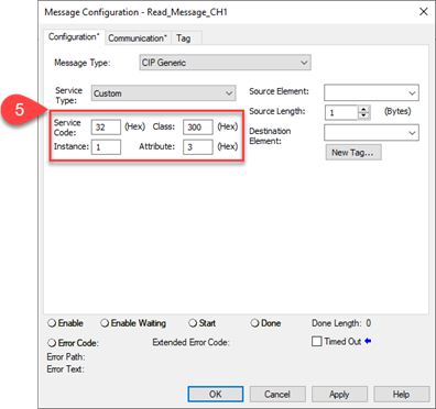
- Go to the “Configuration”.
- Enter the data according to the tables above:
- Service Code: 32 (Hex)
- Class: 300 (Hex)
- Instance: 1, refers to the port where the IO-Link device is connected. In our example it is port 1.
- Attribute: 3 (Hex), as mentioned, refers to the “Slot” number of the IO-Link master. In our example this is slot 3 (0 – CPX-E-EP Interface, 1 – 16 DI Module, 2 – 8 DO Module, 3 – IO-Link Master).
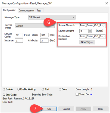
- For this group of options, consider:
- Source Element: For this part, we create an array variable type INT [2]. The first part of this array “Read_Param_Ch1_Source_Element [0]” refers to the Index of the parameter to be read. The second part of the array “Read_Param_Ch1_Source_Element [1]” refers to the Subindex of the parameter to read. Hint: In the Source Element section, you must select the root of the array variable (i.e., Read_Param_Ch1_Source_Element).
- Source Length: 3 (bytes), source length is always “3” for read access.
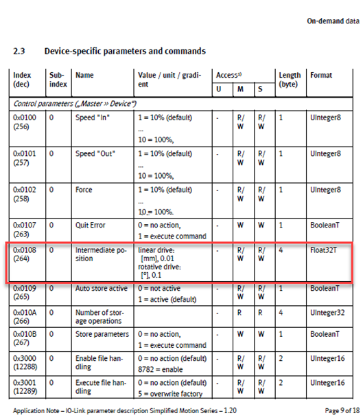
- Destination Element: This part follows the formula Tag of SINT[1+n]. For example, the parameter that we are going to read on our IO-Link device (Intermediate Position) has a length of 4 bytes, therefore, the destination variable will be an array type SINT[5] (i.e., Read_Param_Ch1_Destination_Element). This variable contains in the first byte [0] the status / error code of the request, and from [1] you will find the value of the parameter to read.
- Click on “Apply” then click on “OK”.
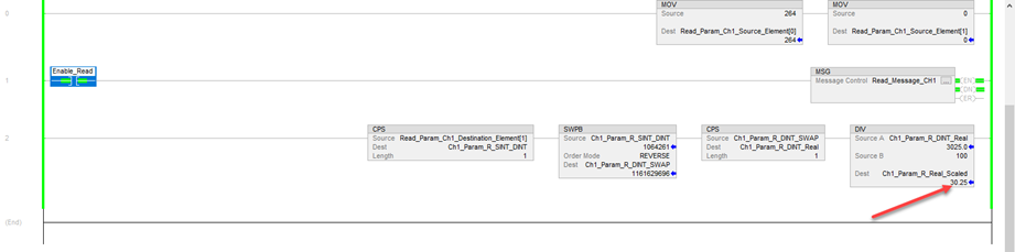
The code may look (for example) like this:
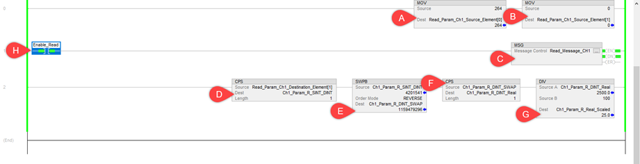
A. MOV instruction to add the value of the “Index”.
B. MOV instruction to add the value of the “Subindex”.
C. MSG described above.
D. CPS to separate the “Status” from the value of the read parameter.
E. SWPB to invert the bytes of the read parameter.
F. CPS to copy the values with the correct bit order to a variable with the parameter data type (e.g., Real).
G. DIV to scale the values in the user unit. The image of the IO-Link device manual fragment shows information to clarify this point.
H. Contact to enable the Mailbox function.
Write parameters to an IO-Link device
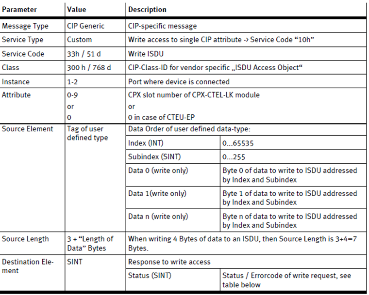
The following table shows the general message instruction requirements to write parameters:
To add the MSG instruction to write parameters, we must:
- Add and name the MSG instruction (usually available in the group of elements: Input / Output). Then open the “Configuration dialog box”.
- Go to the “Communication”.
- Select “Browse…” and locate the CPX-E-EP system bus node in the path.
- Go to the “Configuration”.
- Enter the data according to the tables above:
- Service Code: 33 (Hex)
- Class: 300 (Hex)
- Instance: 1, refers to the port where the IO-Link device is connected. In our example it is port 1.
- Attribute: 3 (Hex), as mentioned, refers to the “Slot” number of the IO-Link master. In our example this is slot 3 (0 – CPX-E-EP Interface, 1 – 16 DI Module, 2 – 8 DO Module, 3 – IO-Link Master).

- For this group of options consider the following information:
- Source Element: Here we will create an array variable type SINT [7]. The first two bytes of this array “Write_Param_Ch1_Source_Element[0] and Write_Param_Ch1_Source_Element[1]” refer to the Index of the parameter to be written. The second part of the array “Read_Param_Ch1_Source_Element [2]” refers to the Subindex of the parameter of the rest of the information to be written. Hint: In the Source Element section you must select the root of the array variable (i.e., Write_Param_Ch1_Source_Element).
- Source Length: 7 (bytes). When writing 4 bytes of data (Intermediate Position parameter as an example) to an ISDU, then Source Length is 3+4=7 bytes.
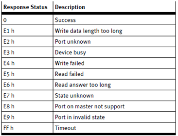
- Destination Element: The response to write access needs a variable type SINT (i.e., Write_Param_Ch1_Destination_Element). This variable contains the status / error code of write request. See the table below.
7. Click on “Apply”. Then click on “OK”.

The code may look (for example) like this:
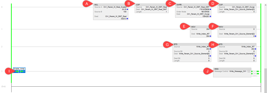
A. MUL instruction to send the user units value (0.01 mm resolution) to a REAL value without scaling factor. For this example, we set the intermediate position on 30.25 mm.
B. COP, used to convert a REAL value to DINT.
C. SWPB, due to bit order in IO-Link, a byte swap to a DINT variable is necessary.
D. COP is used again to separate the DINT information to the array variable (4 type SINT).
E. MOV, to send the index value.
F. MOV, to send the subindex value.
G. The index value is type INT, we must separate it with BTD to 2 SINT variables. (Part 1)
H. The index value is type INT, we must separate it with BTD to 2 SINT variables. (Part 2)
I. Contact to enable the Mailbox function.
J. MSG, described above for the parameter to be written.
Below is a visualization of the parameter 0x0108 (264) sub index (0) Intermediate position. The intermediate position was set at 30.25 mm of the 50 mm of the total stroke of the EPCE-TB IO-Link actuator.
Author:
Alberto Mercado Rios
Festo México – Electric Automation Business Driver