The Benefits of OOP in PLC Programming: A Case Study With a Conveyor System

By Zhou Gong, Control Engineer, Festo
In this blog post, we’re diving into object-oriented programming (OOP) in PLC programming. First, we’ll introduce the basics of OOP — including how it differs from traditional procedural programming in programmable logic controllers (PLC). Then, using a conveyor system example, we’ll illustrate the benefits of OOP in creating a more modular and adaptable program. OOP, for example, enables us to easily modify and extend the conveyor system’s functionality by breaking the functions down into smaller, reusable modules.
Whether you’re new to OOP or an experienced PLC programmer, you’ll gain useful insights into OOP and learn helpful techniques for building more efficient, effective programs.
Why OOP?
Before we use a concrete example, there’s one question we need to think over: why OOP? If I’m doing fine with my procedure programming for years, why use it? The reason is that PLC programs are becoming increasingly complex, and application requirements are changing more frequently than ever before, making it a challenge to create and maintain efficient programs.
Therefore, OOP could provide the following:
- Increased modularity. Breaking down programs into smaller, reusable modules makes the program more adaptable and scalable.
- Flexibility. The program can be easily modified or extended as requirements change.
- Ease of maintenance. The program is easier to understand, test and maintain over time.
Example: A Conveyor System
The key principles of OOP are encapsulation, inheritance and polymorphism. While you can find thousands of articles to explain these principles, the following example offers a deeper understanding.
The example is a simplified scenario of a conveyor system that consists of a conveyor belt and a motor. The goal of this conveyor is to transport boxes from one end to the other. On both sides, there are two light barrier trigger sensors connected to two inputs of a PLC, indicating if there is a box present. The motor of the conveyor needs two digital signals — start and stop — and an analog output for controlling the speed.
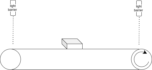
We can define the behavior of the conveyor system as follows:
- If there is no box on the belt, the belt should stop.
- If there is a box at the end of the belt, stop the belt and wait for the box to be picked up.
- If there is no box at the end of the belt but a box at the beginning of the belt, run the belt.
- The speed of the belt is adjustable.
And here are the IO assignments:
- Sensor left: %IX0.0
- Sensor right: %IX0.1
- Motor enable: %QX1.0
- Motor start: %QX1.1
- Speed for motor: %QW2
Conventional Programming
You can immediately initiate straightforward conventional programming by mapping variables and writing the sequence of instructions. The example code below was written in Structured Text, but the code could also be written in Ladder Diagram. Please note that the function demonstrated below is just for illustration purposes and should not be taken too seriously.
PROGRAM ConveyorSystem

VAR

    xBoxAtStart : BOOL AT %IX0.0;

    xBoxAtEnd : BOOL AT NOT %IX0.1;

    xMotorEnabled : BOOL AT %QX1.0 ;

    xMotorStarted : BOOL AT %QX1.1;

    wSpeed : WORD : %QW2;

END_VAR
IF xBoxAtStart THEN
wSpeed := 100; // full speed
xMotorEnabled := TRUE;
xMotorStarted := TRUE;
ELSIF NOT xBoxAtEnd THEN
wSpeed := 50; // reduce speed
xMotorStarted := TRUE;
ELSIF xBoxAtEnd THEN
xMotorStarted := FALSE;
xMotorEnabled := FALSE;
END_IF
While the conventional approach may seem sufficient, what if the customer’s requirements change or the machine needs to be updated?
Changing the light barriers to a camera. Let’s say we want to replace the light barriers with a camera that can scan barcodes. The barcode scanning may not be necessary for the conveyor system, but it will be used in other parts of the machine. Furthermore, the camera can also be used to detect whether there is a box on the conveyor or not. As a result, we can remove the light barriers, and we will have two extra inputs that we can use for other purposes.
Upgrading to servo motors with EtherCAT connectivity. As technology advances, servo motors have become more affordable and efficient, prompting our customer or project manager to suggest upgrading the current motor to a servo motor. The new servo motor will be connected to EtherCAT, a high-performance industrial communication protocol that allows for real-time data exchange between the motor and the PLC.
While these changes may appear to be simple modifications to the current program to meet the new requirements, it’s essential to step back and restructure our program using OOP before making any changes. Although this course may require more effort initially, it pays off significantly in the long run.
The Class Diagram
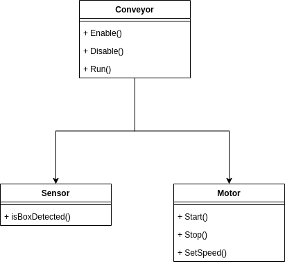
When it comes to OOP, the class diagram is an essential aspect that we can’t overlook. It serves as a useful tool for illustrating the software architecture and can be utilized in planning, development and system documentation. The class diagram represents the basic classes used in our software architecture. There are three classes — Conveyor, Sensor and Motor.
The Conveyor class is a high-level class and includes three methods:
- Enable
- Disable
- Run
The Sensor class includes only one method — isBoxDetected — while the Motor class includes three methods:
- Start
- Stop
- SetSpeed
Based on these three classes, we can create our conveyor system. However, we need to consider the logic that will check the signal from the sensor and control the motor to start or stop. This logic code will be placed inside the Run method of the Conveyor class. For instance, a possible implementation of the Run method is as follows:
Method Run

VAREND_VARIF SensorAtStart.isBoxDetected() THEN
Motor.setSpeed(100); // full speed
Motor.start();ELSIF NOT SensorAtEnd.isBoxDetected() THEN
Motor.setSpeed(50); // reduce speedELSIF SensorAtEnd.isBoxDetected() THEN
Motor.stop();
END_IF
At first glance, the program we have now may look similar to the one we started with, but it is actually quite different. In our Conveyor class, the Run method is only concerned with three aspects of the motor: starting, stopping and setting the speed. The Motor’s “enable” signal is not relevant for the Conveyor. However, we still need the “enable” signal for the Motor, and it will be triggered in the “start” and “stop” methods of the Motor class.
Method Start

VAR

END_VAR
xMotorEnabled := TRUE;
xMotorStarted := TRUE;
Method Stop

VAR

END_VAR
xMotorEnabled := FALSE;
xMotorStarted := FALSE;
You may already be familiar with it, but what we have achieved here is encapsulation. Instead of using the trivial signals “xMotorEnable” and “xMotorStarted” directly in the conveyor program, we have hidden them inside the methods of the Motor class, providing a more straightforward way for the conveyor to use the motor by calling the “start” and “stop” methods.
Encapsulation is not the only benefit of OOP. Another advantage is the ability to easily upgrade or modify existing classes. For example, if we want to upgrade the motor to a servo motor with EtherCAT connectivity, we can create a new class called ServoMotor that inherits from the Motor class. The ServoMotor class will now have all the functions from the Motor class, and we can override the three methods to ensure the logic inside fits the requirements for controlling our servo motor.
The methods might look like this:
// ServoMotor

Method Start

VAR

END_VAR
xPowerOn := TRUE;
xRegulatorOn := TRUE;
xEnable := TRUE;
xStart := TRUE;// ... and more actions
// ServoMotor

Method Stop

VAR

END_VAR
xPowerOn := FALSE;
xRegulatorOn := FALSE;
xEnable := FALSE;
xStart := FALSE;
Our updated class diagram now looks like this:
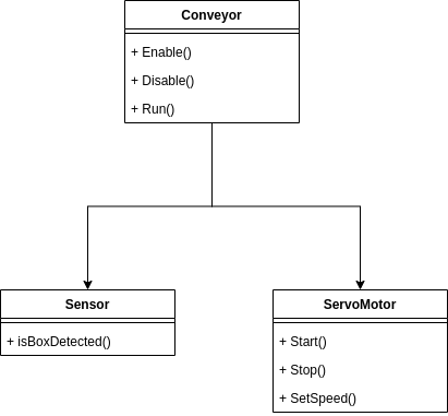
The other parts of the software remain unchanged even after we’ve replaced our motor with a servo motor. By making our software architecture modular, we ensure that our Conveyor class only needs to know that the motor shares the same way of calling its methods (interface), regardless of the specific motor being used.
We can also replace the sensor with a camera very easily.

What We Have Achieved
In short, we’ve used encapsulation to simplify the usage of objects — as we saw with the “start” and “stop” methods of Motor. Through inheritance, we replaced Motor with ServoMotor without modifying other parts of our software.
This approach made our software modular and easier to comprehend and maintain. Please note that the programming approach in this example for OOP is only for demonstration purposes and may not be the best practice. However, if it has helped you understand OOP in PLC programming, it has achieved its purpose.
This article originally appeared on LinkedIn on May 2, 2023.